


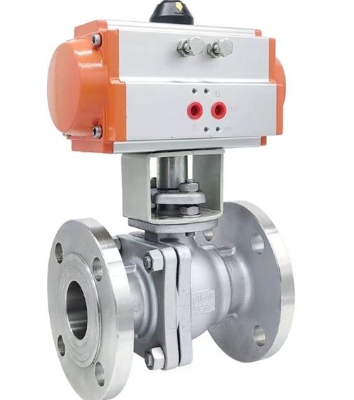
Size a pneumatic ball valve actuator against the valve’s required torque at the minimum air pressure available at the actuator during operation. A compressor’s nominal pressure or an unloaded workshop test is insufficient evidence that the assembled valve will work under its intended process conditions.
When a valve cycles freely before installation but stalls in service, investigate both sides of the selection: the load imposed by the valve and the pneumatic power actually reaching the actuator. This guide focuses on quarter-turn on/off ball valves. It provides an enquiry and diagnostic workflow, rather than a torque rating for any particular KOZO model.
Define the two pressures before comparing equipment
Process pressure acts on the valve and influences its operating load. Instrument-air pressure powers the actuator. These are separate inputs: a valve’s pressure class does not tell you the actuator’s air requirement.
For sizing, establish minimum and maximum supply pressures at the actuator, together with the valve torque requirements. Emerson’s Bettis selection procedures explicitly request both pressure limits and require matching torque at the relevant positions and directions of travel. [1]
Write down where each air-pressure value comes from. “Plant air is normally 6 bar” leaves several questions unanswered: Is that a compressor-room reading? Is it upstream of a local regulator? Was it measured while other equipment operated? Was the actuator moving? A useful specification identifies the measuring point and the operating scenario.
Ask for a valve torque requirement with its conditions attached
Valve size alone is not a sizing basis. Seat material, process conditions and operating frequency can affect the required torque. Bray’s ball-valve selection bulletin uses application, design and frequency considerations when establishing the load for its own valves. Its values should not be transferred to a different manufacturer’s valve. [2]
Request a torque sheet for the proposed configuration. It should identify opening breakaway, running and closing or seating duties as applicable, the pressure conditions used, and any allowances already included. Ask how a long period without operation is treated. Keep torque units consistent throughout the comparison.
For the KOZO Q641F / Q641FH pneumatic flanged ball valve, provide the actual size, seat selection, pressão diferencial, temperature and fail-action requirement before requesting an actuator recommendation. The product family name does not establish a torque value or a spring configuration.
Use a comparison sheet, not one headline torque number
A practical review sheet places the valve requirement beside the available actuator output for the corresponding movement. Include the source and revision of each input so that a later change can be traced.
| Review item | Information to record | Question to resolve |
|---|---|---|
| Opening duty | Required unseating torque and available starting output | Are they based on the same operating case? |
| Travel duty | Running load and output across travel | Is there an intermediate position that governs selection? |
| Closing duty | Seating requirement and available closing output | Does the required final position remain achievable? |
| Pressure range | Minimum sizing pressure and maximum supply | Are both limits covered by the selected assembly? |
| Allowances | Application factors and agreed design margin | Have allowances been omitted or counted twice? |
Por exemplo, consider an entirely hypothetical comparison: an agreed opening requirement is 100 N·m, while a candidate actuator’s relevant output is 120 N·m at the nominal supply but only 85 N·m at the specified minimum. The nominal-pressure result does not make that candidate acceptable for the minimum-pressure case. These numbers illustrate the comparison only; they are not KOZO product data.
Resolve the failed comparison by reviewing the selection and the air-supply specification together. Do not silently replace the guaranteed minimum with the higher pressure that happens to be available during a demonstration.
Spring return adds a second duty to verify
A spring-return assembly needs adequate output for both the air-powered movement and the spring-powered movement. For a fail-close arrangement, reaching the closed position on loss of air is a separate requirement from opening successfully during normal operation. Fail-open arrangements require the corresponding reverse review. The Bray selection bulletin highlights checking both air-stroke and spring-stroke end duties for its ball-valve combinations. [2]
Record the exact actuator model, spring set, mounting direction and required failure position. Avoid accepting a quotation that says only “spring return” without a configuration record. Ask the supplier to confirm the complete assembly’s response to loss of air and loss of electrical signal separately; the control arrangement affects what those events mean.
Bray’s Series 98C technical manual also distinguishes pressure-powered and spring-powered torque values and includes maximum allowable stem torque among its sizing terminology. Those distinctions are useful review concepts, but its torque charts apply to that actuator family. [3]
If the valve stalls, collect evidence before increasing pressure
Begin with the equipment identification and the exact symptom. Does the valve fail to start, stop partway, move slowly throughout, or fail only in one direction? Note whether the problem follows a process change, maintenance work or a change in air-system demand.
The following sequence is a suggested investigation record for the responsible maintenance and engineering team:
- Save the original sizing sheet, regulator setting and control schematic. Record the last known satisfactory operating conditions.
- Document pressure near the actuator during a permitted operating test, alongside valve position and the command signal.
- Check the air path against the specified tubing, acessórios, filter-regulator and pilot valve. Include the exhaust route in the inspection.
- Compare the observed conditions with the assumptions in the sizing sheet. Keep measured values separate from estimates.
- Refer unexplained resistance or binding for mechanical inspection under the appropriate isolation procedure.
Bray’s Series 92/93 troubleshooting guidance identifies low supply pressure, internal leakage, coupling misalignment and insufficient supply flow among possible causes of poor operation. This supports checking the assembly rather than diagnosing every stall as an undersized actuator. [4]
Before removing an actuator or opening pneumatic components, isolate process and control energy under the site procedure. Spring-return units contain stored mechanical energy; use the exact manufacturer’s instructions and qualified personnel for any spring-related work.
Pressure availability and operating speed need separate checks
An actuator selection also needs a suitable pneumatic circuit. Tubing length, pressure losses and pilot-valve capacity influence how the unit responds. Festo’s process-valve automation guidance treats these accessories and their interaction as part of selecting the required switching performance. [5]
Specify required opening and closing times separately, and explain how they will be measured. A test record should distinguish command delay from actual valve travel. Avoid treating a position indication alone as proof of an acceptable seat-leakage result; these are different acceptance checks.
Increasing supply pressure is not an unrestricted troubleshooting method. Review the actuator’s pressure limit and the assembly’s allowable mechanical loads before any approved setting change. A larger actuator also needs a fresh review of the stem, coupling and bracket rather than being accepted solely because its output is higher.
Send an enquiry that can produce a defensible selection
Prepare one package containing:
- Valve identification, tamanho, conexão, seat and trim configuration.
- Fluid, temperatura, operating differential pressure and relevant upset cases.
- Torque requirements, their source, and the allowances already included.
- Minimum, normal and maximum instrument-air pressure at the assembly.
- Required fail action, cycle frequency and opening and closing times.
- Control schematic, accessory requirements and environmental conditions.
- For a retrofit, photographs, mounting dimensions and existing actuator details.
For a Q644F / Q645F pneumatic three-way ball valve, also identify the required port connections in each position. Do not assume a two-way isolation valve’s selection sheet covers a three-way routing duty.
Questions to settle before placing the order
Can an existing actuator be reused?
Possibly, but retain it only after reviewing the new valve load, supply range, fail action and mechanical interfaces. Matching nominal valve size is insufficient documentation for reuse.
Is there one safety factor for every application?
No universal value is specified here. Agree the allowance with the valve and actuator suppliers for the duty, and state whether it is already included in the submitted torque requirement.
What should the supplier return?
Request an identifiable valve-actuator configuration, the sizing comparison, pressure limits, accessory list, fail-action description and agreed functional tests. These make the selection reviewable when equipment or process conditions change.
Planning an automated ball valve? Send KOZO your valve duty and instrument-air range, with unknown values clearly marked, for a configuration review.