

Complete Guide to the Working Principles of Hydraulic Control Valves
What is a hydraulic control valve?
Hydraulic control valve is a general term for valves. It is a type of automatic control valve that is composed of a main valve and external auxiliary components such as a needle valve and a pilot valve. It does not require an external power source and relies entirely on the pressure difference △P between the upstream and downstream of the pipeline system as power to realize automatic opening, closing and adjustment of the valve.
Working principle of hydraulic control valve
Hydraulic control valves are widely used in domestic water supply, fire protection systems and industrial water supply systems. They can achieve multiple functions such as pressure reduction and pressure stabilization, pressure relief and pressure maintenance, slow closing check, and liquid level control.
Detailed explanation of the working principle of hydraulic control valve
core working logic
The core working principle of the hydraulic control valve is: powered by the pressure difference ΔP between the upstream and downstream of the pipeline system and controlled by the pilot valve, the diaphragm (piston) operates hydraulically differentially and is completely automatically adjusted by hydraulics, so that the main valve disc is fully open, fully closed or in a regulated state.
There are three main working states of hydraulic control valves:
Working status Control room status Valve disc position
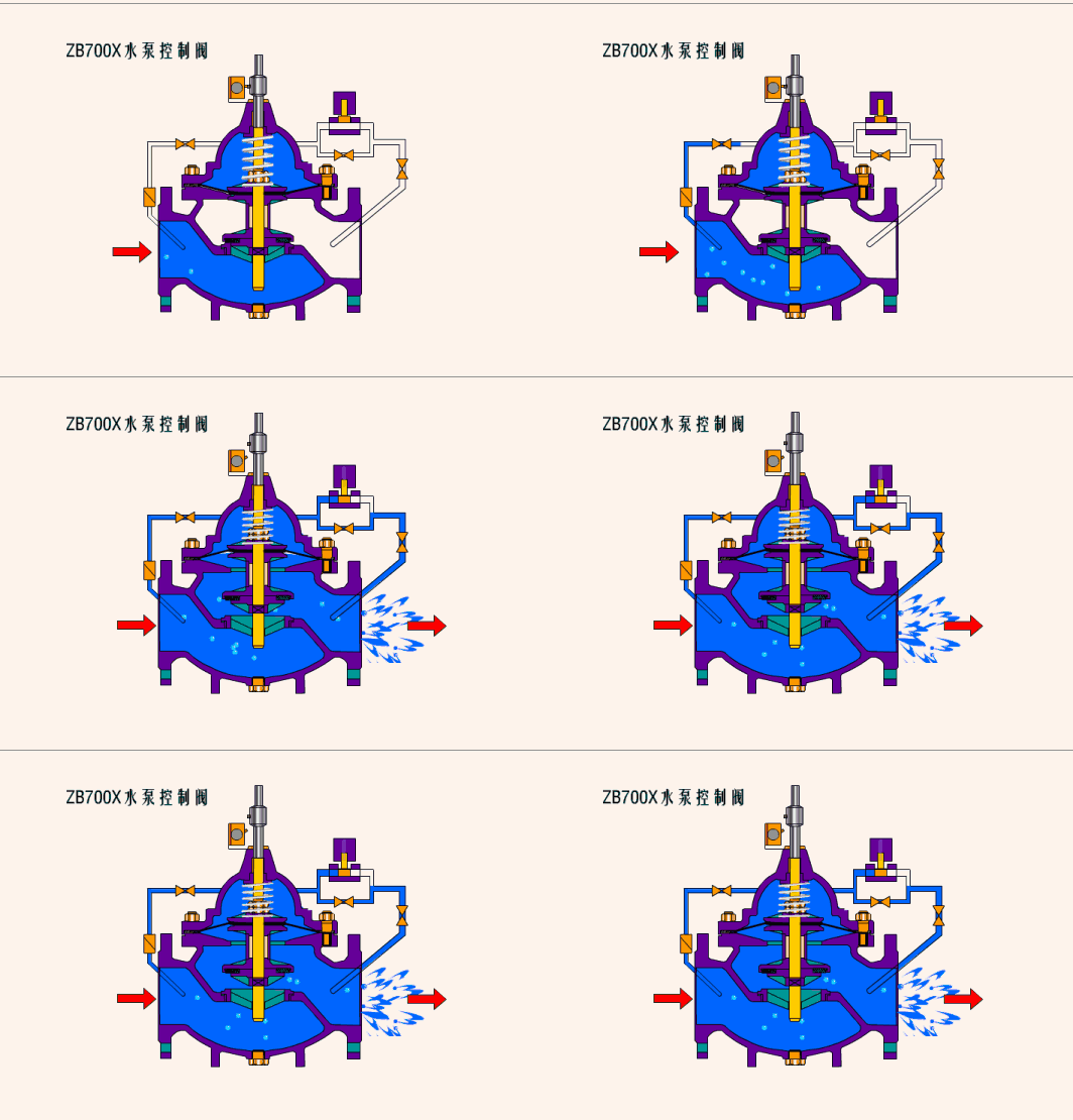
In the open state, the pressure water in the control room is discharged to the low pressure area, and the valve disc is pushed open by the bottom pressure to fully open.
In the closed state, the pressure water in the control room cannot be discharged. The valve disc is pressed fully closed by the pressure from above.
Adjustment state: The pressure in the control chamber is between the inlet and outlet. The valve disc is in the intermediate adjustment position.
Opening process
When the pressure water entering the control chamber above the diaphragm (piston) is discharged to the atmosphere or downstream low-pressure area, the pressure value acting on the bottom of the valve disc and below the diaphragm is greater than the pressure value above. Relying on the pressure of the pipeline medium, the main valve disc is pushed to the fully open position.
shutdown process
When the pressure water entering the control chamber above the diaphragm (piston) cannot be discharged to the atmosphere or the downstream low-pressure area, the pressure value acting on the top of the diaphragm (piston) is greater than the pressure value below. The medium in the pipeline presses the main valve disc to the fully closed position.
Regulating state
When the pressure value in the control chamber above the diaphragm (piston) is between the inlet pressure and the outlet pressure, the main valve disc is in a regulating state. Its adjustment position depends on the joint control effect of the needle valve and the adjustable pilot valve in the attached piping system. The adjustable pilot valve can automatically adjust the opening of its own valve port through the downstream outlet pressure and changes in it, thereby changing the pressure value in the control chamber above the diaphragm (piston) and controlling the adjustment position of the main valve disc.
Structural composition of hydraulic control valve
The hydraulic control valve mainly consists of the following parts:
Main valve: the main part of the valve, including core components such as valve body, valve cover, diaphragm (or piston), and valve disc.
Pilot valve: Acts according to changes in the control object (water level, pressure, و غیره) to control the opening, closing and adjustment of the main valve
Needle valve: adjusts the inlet water flow rate in the control room and affects the action speed of the valve
Ball valve: used to cut off or connect control pipelines
Pressure gauge: monitor the pressure status of the inlet, outlet and control room
Micro filter: protects the pilot valve and needle valve from being blocked by impurities
Hydraulic control valves can be divided into two types according to their structures: diaphragm type and piston type. Their working principles are the same. The action of the main valve is realized through the pressure difference between the upper and lower sides of the diaphragm (piston).
Main types of hydraulic control valves
Depending on the purpose, function and place of use, the hydraulic control valve can evolve into a variety of functional valves:
Valve Type Main Functions Typical Applications
Remote control float valve controls liquid level and automatically replenishes water in pools and water towers
Pressure reducing valve to stabilize downstream pressure in high-rise building water supply systems
Slow-closing check valve prevents backflow and eliminates water hammer water pump outlet
Flow control valve Limit flow Pipe flow regulation
Pressure maintaining/pressure relief valve maintains or releases pressure Fire protection system, pipe network protection
Hydraulic electric control valve remote control opening and closing automatic control system
Water pump control valve, water pump start and stop control, pump station automation
Emergency shut-off valve, emergency cut-off, gas and chemical pipelines
Design features of hydraulic control valves
1. Flexible pilot valve combination
Since there are many types of pilot valves, they can be used alone or in combination, so that the main valve can have the function of regulating water level, water pressure, flow, و غیره. individually or in combination. Nearly 30 functions can be derived through different combinations of pilot valves and system small pipelines.
2. Slow closing characteristics
When the hydraulic control valve is close to fully closed, the valve disc movement accelerates and water hammer impact is prone to occur. بنابراین, when the valve is close to fully closed, the slower the valve action, the better. A throttling mechanism can be set on the valve disc to extend the closing time and reduce water hammer impact.
3. Anti-clogging design
The throttling and action parts of the pilot valve should try to avoid setting particularly small-diameter orifices to avoid clogging. If necessary, it is necessary to install a filter, perform regular maintenance and set up a bypass pipeline.
Limitations of hydraulic control valves
Large pressure loss: The main valve body is similar to a stop valve. When the valve is fully open, its pressure loss is much larger than that of other valves. And the closer each opening loss coefficient is to the fully closed state, the more it increases sharply, and the larger the valve diameter, the more significant it is.
Response speed: Hydraulic control valves rely on medium pressure to operate. The response speed is relatively slow and is not suitable for working conditions that require fast response.
Typical applications of hydraulic control valves
Hydraulic control valves are widely used in:
Domestic water supply system: pressure reduction and stabilization, liquid level control
Fire water supply system: pressure relief and pressure maintenance, water pump control
Industrial water supply system: flow regulation, pressure control
Municipal water supply network: zoned water supply, pressure management
For more technical information on hydraulic control valve selection or specific applications, please feel free to contact our engineering team.
Hydraulic control valves, working principle of hydraulic control valves, pressure reducing valves, remote control float valves, slow-closing check valves, water pump control valves, industrial valves, water supply systems, level control